Utilities
The module provides additional functions to modify existing model in MIDAS CIVIL NX
Note.
All the codes below assumes the initial import and MAPI Key definition.
from midas_civil import *
MAPI_KEY('eyJ1ciI6InN1bWl0QG1pZGFzaXQuY29tIiwicGciO252k81571d')
LineToPlate
utils.LineToPlate(nDiv:int = 10 , mSizeDiv:float = 0, bRigdLnk:bool=True , meshSize:float=0.5, elemList:list=None)
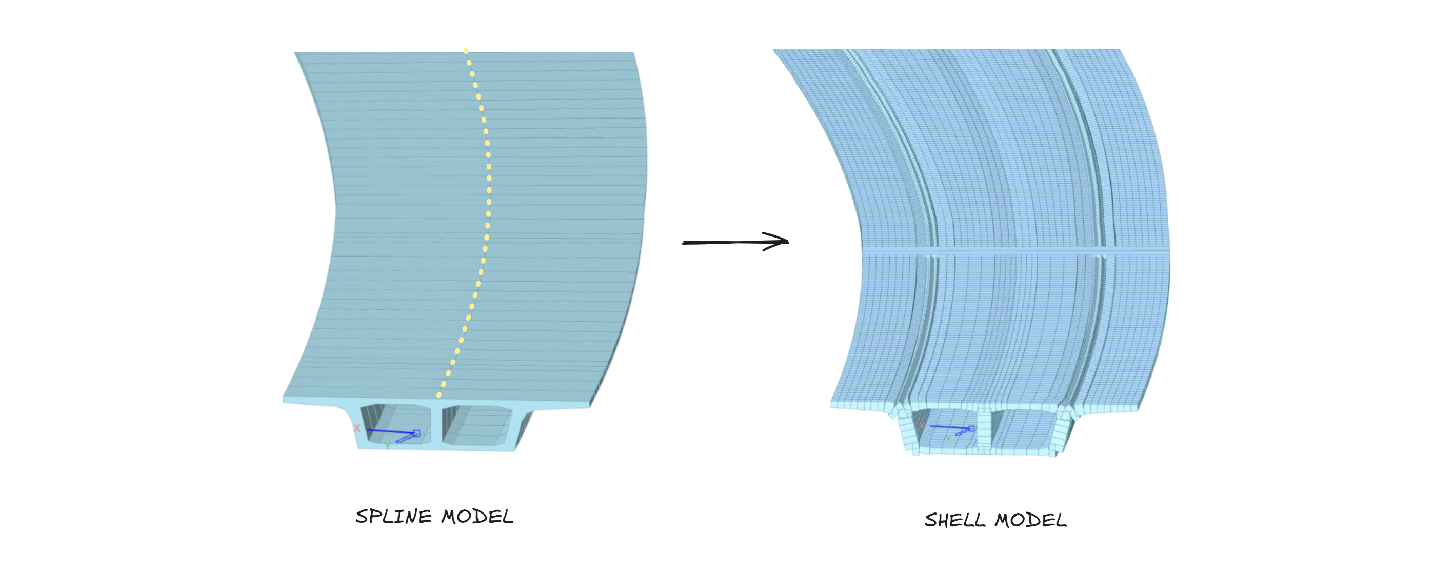
The LineToPlate converts selected or specified line elements into shell (plate) elements in CIVIL NX.
It provides flexible options for controlling the mesh density, division method, and boundary connectivity between elements.
Parameters
nDiv : int: Number of divisions along the span. Used whenmSizeDiv = 0.mSizeDiv : float: Division control based on mesh size (in meters).bRigdLnk : bool: Whether to create rigid links at the ends of the span for connectivity and boundary constraint.
True: Create rigid links at end. | False: No links are created.meshSize : float: Desired mesh size (in meters) for the resulting plate elements. Controls plate element fineness.elemList : list[int]: List of element IDs to be converted. IfNone, the currently selected elements in CIVIL NX are used.
Note.
Either nDiv or mSizeDiv should be specified (not both simultaneously):
1. Use nDiv when we want an exact number of divisions.
2. Use mSizeDiv when we want divisions based on mesh size.
To use with tapersections assigned to a Tapered Group, we first need to Convert them into individual tapered section
Examples
# USE ONLY ONE AT A TIME

# Example 1: Convert selected line elements with 10 divisions
utils.LineToPlate(20)

# Example 2: Convert lines based on mesh size of 0.25 m
utils.LineToPlate(nDiv=0, mSizeDiv=0.25)

# Example 3: Convert specific element list without rigid links
utils.LineToPlate(elemList=[101, 102, 103], bRigdLnk=False)

# Example 4: Use custom mesh size for the plate elements
utils.LineToPlate(mSizeDiv=0.5,meshSize=0.5)
Supported Sections
Uniform and Tapered sections mentioned below can be converted to shell representation.
| NAME | SHAPE |
|---|---|
| Angle | "L" |
| Channel | "C" |
| H/I-Section | "H" |
| T-Section | "T" |
| Box | "B" |
| Pipe | "P" |
| Solid Rectangle | "SB" |
| PSC 1-2 Cell | "1-CEL" & "2-CEL" |
| Steel Tub Type 1 | "Tub" |
Alignment
utils.Alignment(points:list, type: str = 'cubic')
The Alignment class creates a smooth curve (alignment) that interpolates between a series of given (x, y) points. It provides an interpolated curve representation (e.g. cubic spline, Akima, Makima, PCHIP) that can be later used to:
- Transform points from one alignment system to another.
Parameters
points : list: A list of coordinate pairs [[x₁, y₁], [x₂, y₂], ...] defining the alignment path.type : str: The type of interpolation used to generate the alignment curve. Options:
1 :cubic- Cubic Spline (default)
2 :akima- Akima spline
3 :makima- Modified Akima spline
4 :pchip- Piecewise Cubic Hermite Interpolating Polynomial
Note.
Ensure that x-values in points are monotonic (increasing) to avoid errors in interpolation.
Object Attributes
PT_X: Input points X-coordinates
PT_Y: Input points Y-coordinates
TOTALLENGTH: Total length of the Alignment
Object Functions
getPoint: Returns (x,y) point at specific distance from start
getSlope: Returns slope(in radians) at specific distance from start
Alignment.transformPoint
utils.Alignment.transformPoint(point, initial_align, final_align)
The transformPoint method maps a given point from one alignment to another.
It is used to realign geometric data — for instance, transforming model node coordinates from an original (initial) alignment to a modified (final) alignment.
Parameters
point : tuple(float,float): The coordinate (x, y) of the point to transform.initial_align : Alignment: The original alignment object that defines the reference geometry before modification.initial_align : Alignment: The target alignment object defining the new geometry.
Examples
Obtaining new location
from midas_civil import *
# Define two alignments
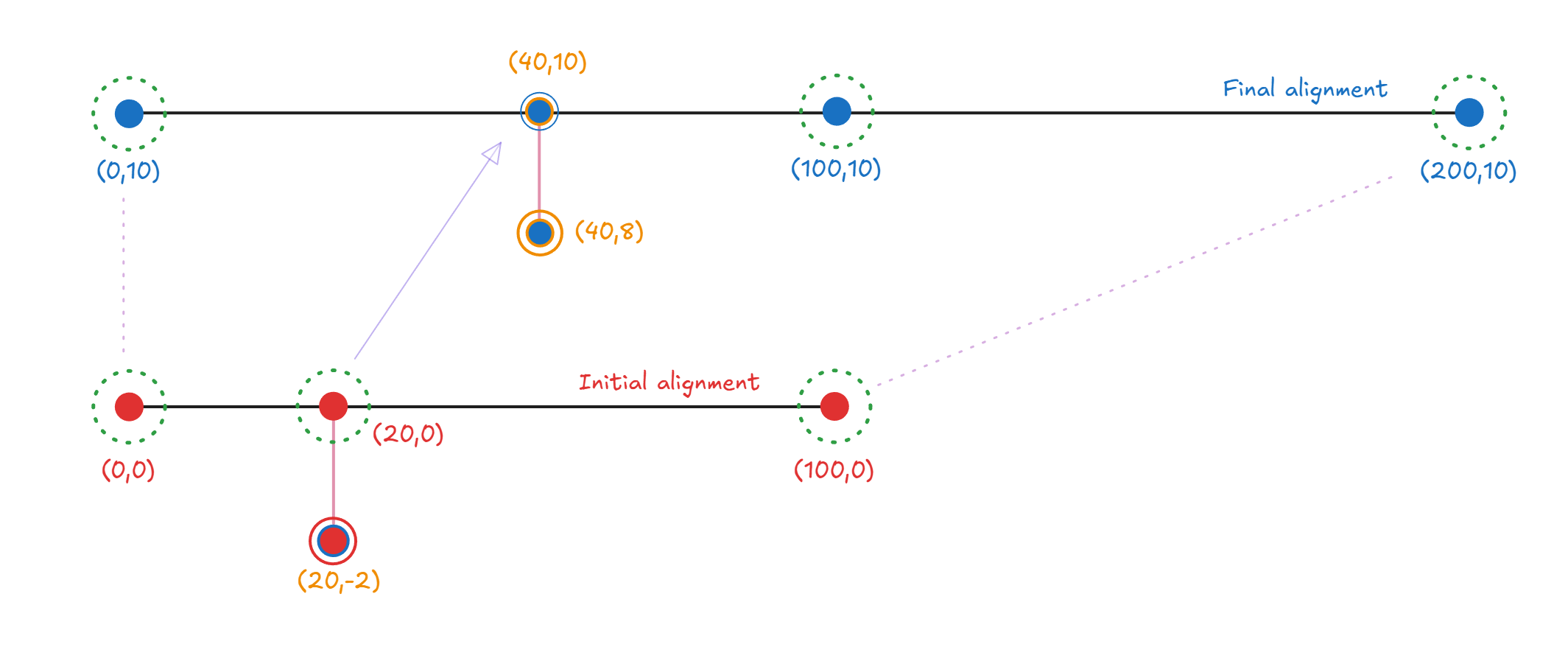
initial_align = utils.Alignment([[0, 0], [20, 0], [100, 0]])
final_align = utils.Alignment([[0, 10], [100, 10], [200, 10]])
# Transform a single point from the initial to the final alignment
pt_original = (20, -2)
pt_transformed = utils.Alignment.transformPoint(pt_original, initial_align, final_align)
print(pt_transformed)
# Example output: (40, 8)
Modify alignment
# Modifies existing model
from midas_civil import *

initial_align = utils.Alignment([[0,0],[80,-1.6],[160,-14.5]])
final_align = utils.Alignment([[0,0],[80,-5],[140,20]])

Node.sync()

for node in Node.nodes:
    node.X , node.Y = utils.Alignment.transformPoint((node.X,node.Y),initial_align,final_align)
Node.create()
RC Grillage
utils.RC_Grillage(span_length = 20, width = 8, support:Literal['fix','pin']='fix', dia_no=2,start_loc = [0,0,0], girder_depth = 0, girder_width = 0, girder_no = 0, web_thk = 0, slab_thk = 0, dia_depth = 0, dia_width = 0, overhang = 0, skew = 0, mat_E = 30_000_000)
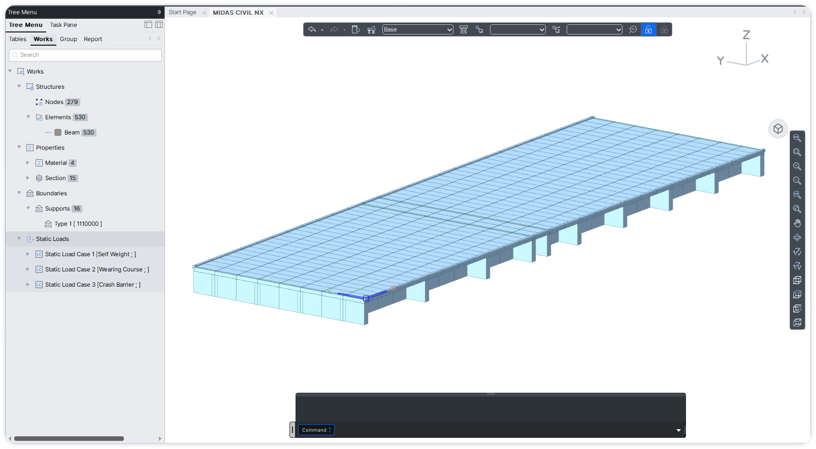
RC Grillage Utility wizard to generate an RC grillage model in CIVIL NX with configurable geometry, supports, and material properties.
Use Model.create() at the end to send data to CIVIL NX.
Parameters
span_length : float: Span length of the structure (default = 20).width : float: Overall deck width (default = 8).-
support : {'fix','pin'}: Support condition at span ends.
fix: Fixed support | pin: Pinned support -
dia_no : int: Number of diaphragms (default = 2). start_loc : list[float]: Starting coordinates[x, y, z]for grillage placement.girder_depth : float: Depth of girder section.girder_width : float: Width of girder section.girder_no : int: Number of longitudinal girders.web_thk : float: Thickness of girder web.slab_thk : float: Thickness of deck slab.dia_depth : float: Depth of diaphragm.dia_width : float: Width of diaphragm.overhang : float: Overhang length beyond outer girders.skew : float: Skew angle in degrees.mat_E : float: Modulus of elasticity of material (default = 30,000,000).
from midas_civil import *

utils.RC_Grillage(12,8,'pin',4,start_loc=[0,0,0])
utils.RC_Grillage(15,8,'pin',6,start_loc=[11,0,0])

Model.create()